Hello,
I work on the degradation of a material under incident flux (in particular radiation).
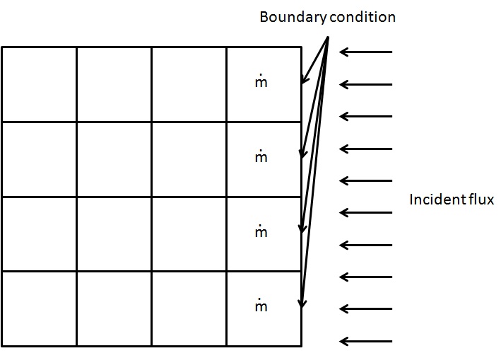
I mesh a slab, with on one face, boundary condition for the incident flux and for the other faces, boundary condition for convective loss.
When the material reaches its temperature of pyrolisis at its heated face, I calculate the mass flow \dot{m} of pyrolisis in each neighbouring cell.
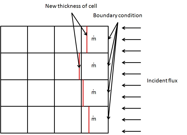
I then calculate the remaining thickness of the cell due to this mass flow.
When the thickness loss becomes higher than the thickness of the first cell, I change the thermal properties of the cell from those of the material to those of the air. I desactivate the incident flux at this boundary condition and I have to create a new boundary condition at the position of internal face.
How can I create this boundary condition? Have I to define all the concerned internal face to boundary condition when I created my mesh and modify the type of the boundary conditions in my code (wall when its a real boundary condition, other(inlet, outlet?..) when its internal face)?
Is there another way to do that ?
Thank you for your answer!
Hello,
I can’t check the images from work (our proxy prevents it), so I may be wrong, but at first description of your case, maybe using ALE mesh movement so as to move the boundary inwards according to the removed thickness would seem a simpler solution.
Regards,
Yvan
I edit my post and joined the image for more clarification.
With ALE mesh movement, I can have none regular movement of my boundary condition? I have to define all the concerned internal faces as boundary conditions at the begining of the calculation? (in order to have the good number of nfabor faces of boundary condition)
Hello,
With ALE mesh movement, you can prescribe the exact movement of the part of the boundary you are interested in, so it may be irregular of you choose (if that is your question).
This should avoid changing between boundary and interior faces. I any case, you cannot apply boundary conditions to interior faces, and you would need a lot of work to do so (duplicating a lot of code, adapting wall laws if you have turbulence, adapting radiation, …). Removing cells from the mesh (using cs_user_mes_modify in cs_user_mesh.c) would probably be simpler, but you would still have to update all array sizes and matching arrays (rtp, …), which would be quite complex.
Regards,
Yvan
Thank you for your answer, I’ll look at ALE mesh movement module.
Some questions about ALE :
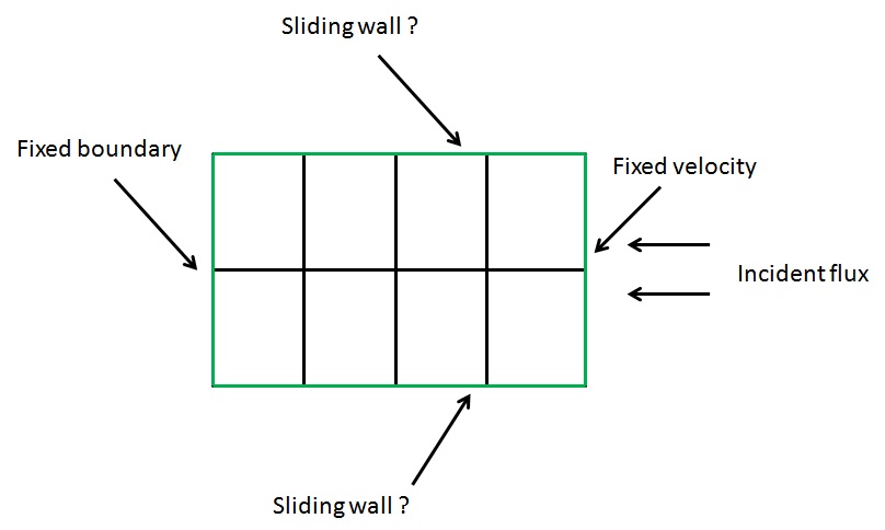
What is a sliding wall?
For my exemple, those boundary condition can be good? Boundary faces are in green, incident flux coming from the right (so pyrolysis will happens on the boundary condition on the right). I want to move the boundary face from green to red line. (it can be non homogeneous but I see in usalcl.f90 how to modify that)
What will be the new mesh after the moving of boundary conditions?
Like that?
Or that? (I think it’s for displacement of node no?)
I use paraview to see the post precessing, but with all the tests I made, I never see any change in the mesh, so I don’t know if it really work (I see that the volume of cells varies in saturne, but no change in paraview)
I also have a warning in the listing :
variablemesh_u
resolution of linear system could fail
iresol ( 5) = 1
and the variable is not advected (iconv = 0)
I check cs_user_parameters and gui I don’t see how and where I can suppress this warning.
Thank you in advance.
I manage to see the result in paraview, I let fixed mesh in the time dependency of the writer of output.
With Transcient coordinates, it works better 
I can make some test to see what is the best solution for my boundary condition.
Hello,
A sliding wall will not be a useful solution for you: it is intended for use with a fixed mesh, and simply adapts the no-slip or friction computation on that wall as if it were moving (useful for example for the ground under a vehicle, if the domain is fixed around that vehicle).
“True” moving mesh (or more complex mesh modification) is what you need, and ALE is probably much simpler than removing cells if applicable.
Regards,
Yvan
Hello,
After some test, I managed to move the mesh in the way I want (with depale). I do it on boundary face and internal face. What would you advice to me for minimal volume of cells to keep?
Thank you!
Hello,
It depends on the initial mesh quality, and modified quality. If the deformation is relatively uniform and the mesh remains relatively orthogonal, you can deform it quite a bit with no risk. The things you need to avoid are cells which become inverted, or “tangled” after deformation, or deformations which lead to strongly irregular cells, as they will adversely affect the mesh quality.
I am not sure depale should be used to prescribe movement of internal faces (I believe this is done by ALE based on the boundary deformation). If you do it yourself, you probably have better control over the mesh quality, but I am not sure whether some terms related to mesh velocity might be counted one too many or too few times (though if mesh velocity is negligible, you might not care). I do not know this part of the code very well, so I’ll let others confirm or contradict me here (the documentation might also help).
Regards,
Yvan
I use a displacement of internal face in order to avoid negative volume on first cell. With moving wall (by fixed velocity), only the boundary condition moves and so at a moment, the boundary condition moves enough to be at the same place of the first internal face (which can create negative volume if boundary condition moves behind the first internal face).
As my cells are originally orthogonal and keep the same orientation for the moving face, I obtain then a new orthogonal cell with different volume. So I seems to keep good quality.
I’ll give you more feedback later!
I’ve got some new questions about my problem.
I simulate the degradation of a solid (yes, it’s strange to use a CFD code to simulate a solid, but I have the habit of Code_Saturne). So, in my solid, there is no velocity. Till I don’t modify the mesh, I have no velocity and no pressure inside my solid. But when I start moving the mesh, a velocity and a pressure appear inside my solid. I try to put high viscosity (1e+20) but it remains a very small velocity (something like 1e-9).
Is there a way to not calculate the flow, or clipping the value of velocity/pressure to 0?
Hello,
You can clip all you want in cs_user_extra_operations.f90, but it might not be sufficient.
The same, you can set iconv(iu), iconv(iv), iconv(iw) to 0 to deactivate convection for velocity (and idiff or idifft to deactivate diffusion or turbulent diffusion), but I am not sure this will work, as velocity-pressure coupling may still occur, and the fact you are using ALE might lead to other terms being accounted for automatically.
So you might want to try either one of these options, but I’m not sure of the results (I would try deactivating convection first). If none work, we’ll try to think of something else.
Regards,
Yvan
Thank you for your answer, I’ll try that and give you a feedback.