Hello, does anyone use pointwise to generate mesh and then import to CS?
I selected cgns solver in pointwise and set two spanwise BCs as unspecified or user defined.
But always get an error:
“First face with boundary condition definition error (out of 306960)
has boundary condition type 0, center (2.85521, -0.00179797, 0.09875)”
I attached the listing file.
I am running an simulation of an aerofoil section, spanwise length is 0.1 chord length and both spanwise BCs are periodic.
Any helping comments are highly appreciated!!! listing.txt (34.8 KB)
Hello, I defined my boundary conditions. Please see attached for my xml files.
It is the same xml file when I was using ICEM generated mesh which can be read correctly.
Do you know why it is not running with pointwise generated mesh?
I do not know what your mesh looks like, but aside from the LEFT and RIGHT groups (which you seem to use for periodicity, INLET includes 65800 faces, OUTLET 22120, and AIRFOIL 79920, so the sum does not match the total of 474800 boundary faces in your final mesh.
So you probably missed some boundary group definitions.
Did you check the error postprocessing as recommended in the listing ? It should show you where definitions are missing.
Thank you, Yvan. I visualized the error postprocessing as you suggested, please see attached.
It seems that code saturne treated all the connections inside the domain as boundaries. The connections in the domain are supposed to treated as interior cells. I believe this should be the problem.
To solve this problem, I can try to put all the connections as one boundary group, but what boundary conditions should I set up in CS? obviously it is neither inflow, outflow nor wall. I would like to set them as interior but do not know how. Please let me know if you have a good suggestion.
I assume you mean there is a warning in preprocess.log, and yes, the warning is
“Warning=======
The CGNS mesh read contains multizone (“one to one”)
vertex equivalences which are not automatically handled
by the Preprocessor.
→ Use an appropriate joining option”
In terms of adding a mesh joing operation, do you mean Face joining (optional) under the Meshes selection? which in xml file is
"
<face_joining name=“1”>
0.1
25
all %% I assume this is the selection criteria you suggested
1
1
</face_joining>
"
When checking the joined mesh quality,
“Criterion 3: Least-Squares Gradient Quality: Number of bad cells detected: 268760 → 1 %”
Every time step takes much longer time due to too many pressure iteration steps
“Variable Rhs norm N_iter Norm. residual derive Time residual
Pressure 0.60925E-02 3435 0.11973E+01 0.27027E+01 0.20117E+06”
I assume this is caused by the mesh joining. Any way to improve?
The least-squares gradient quality might not be so bad if only 1% of cells are “bad”, but I recommend visualizing the mesh quality to see where cells are bad: it may be due to the joining, but also to other factors, such as warping.
The number of iterations for pressure seems pretty high, especially if you are using multigrid and this is a “pseudo-equivalent” (number of iterations), but the first iterations might be more costly, and there might be other factors, such as gradient reconstruction choice, and especially time step/CFL aspects.
Here again, postprocessing/visualizing after a few iterations will probably provide more insight.
Hello, I managed to fix these two problems by adjusting the mesh zones. Now the code is running. Thank you very much.
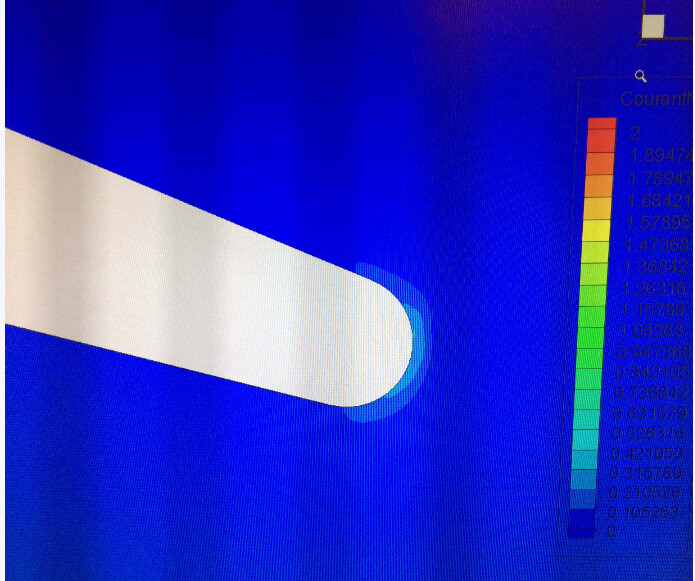
However, the velocity and CFL number blow up after several hundred steps even if I set the time step as a very small value. I attached the CFL contours of 100, 200 and 300 time steps, after that the velocity diverged from the near trailing edge zone. I think this is probably a initial flow behavior of a circular trailing edge aerofoil, because I used same settings to a sharp trailing edge aerofoil and it runs fine.
I will appreciate if you can give me some suggestions on this problem.